
AUGUST 2026 UPDATE
AUGUST 2026
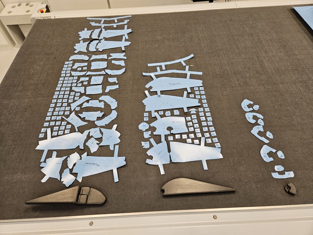
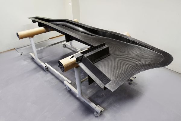
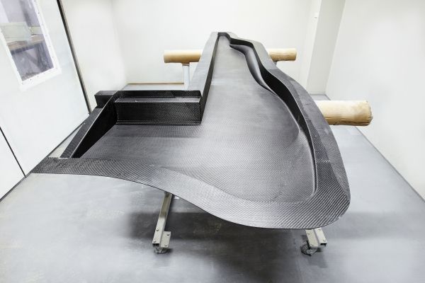
FIRST ARTICLES
As we continue to push through 2026, development is progressing well and many goals are being achieved.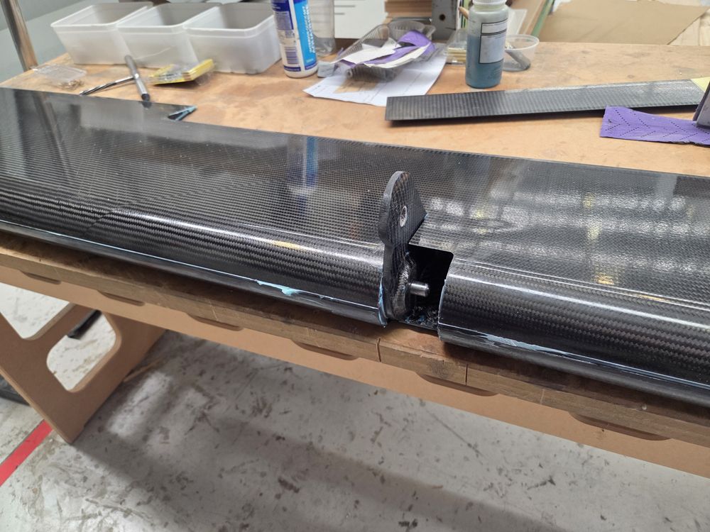
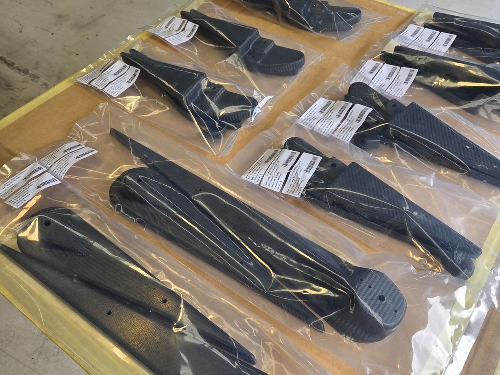
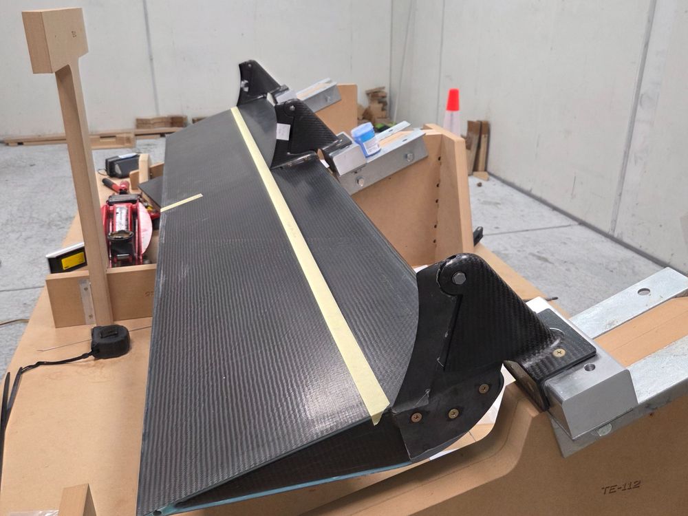
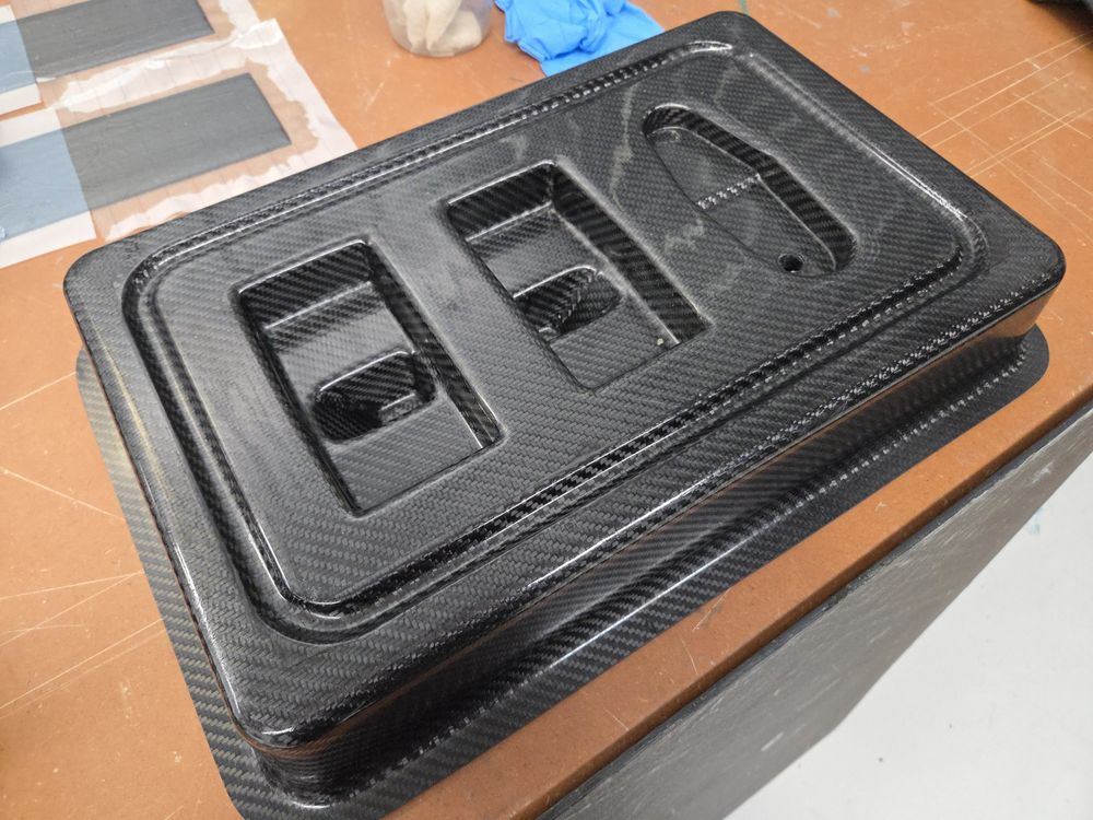
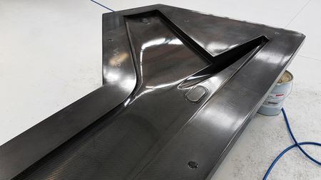
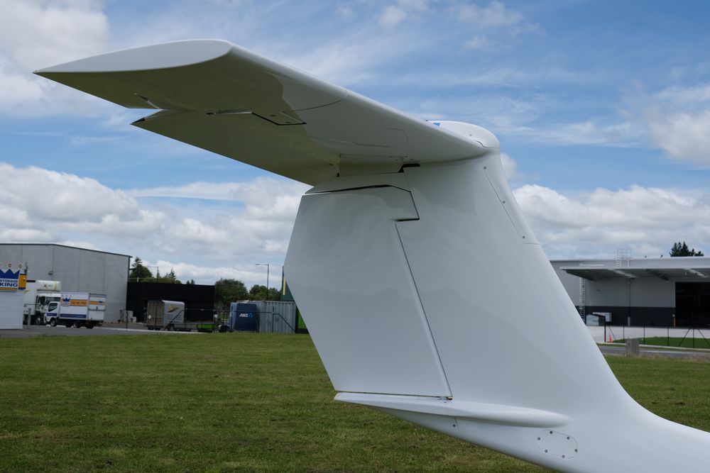
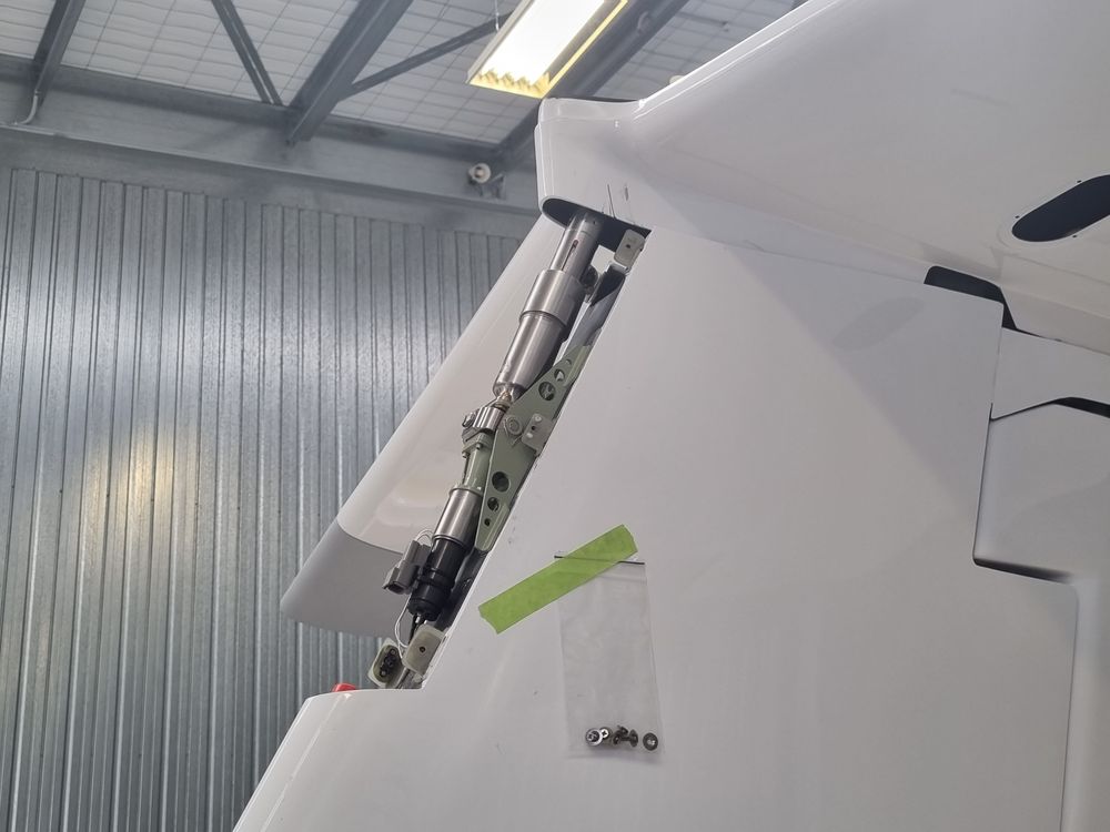
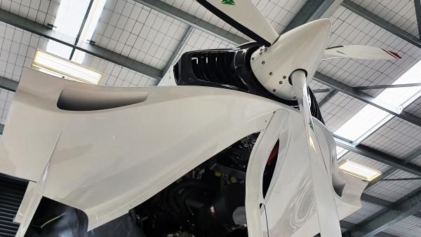
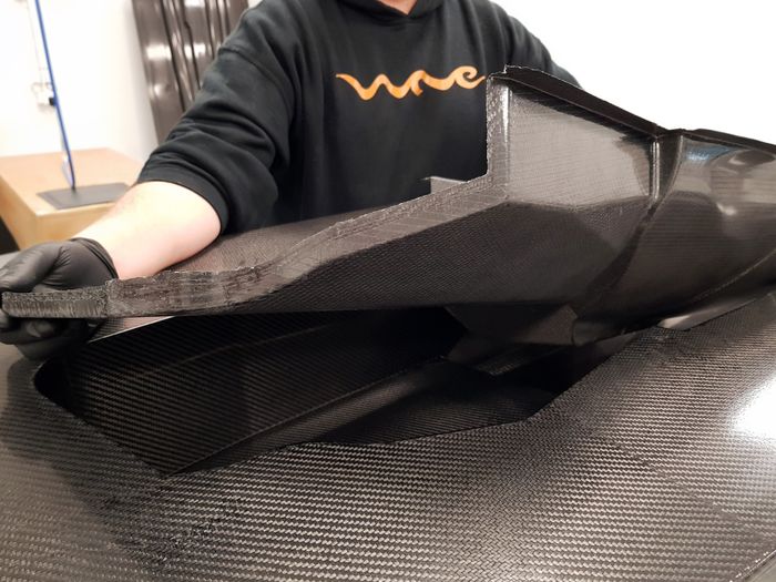
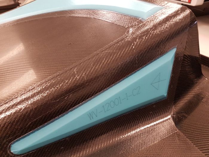
Above: Elevator pushrod attachment bracket.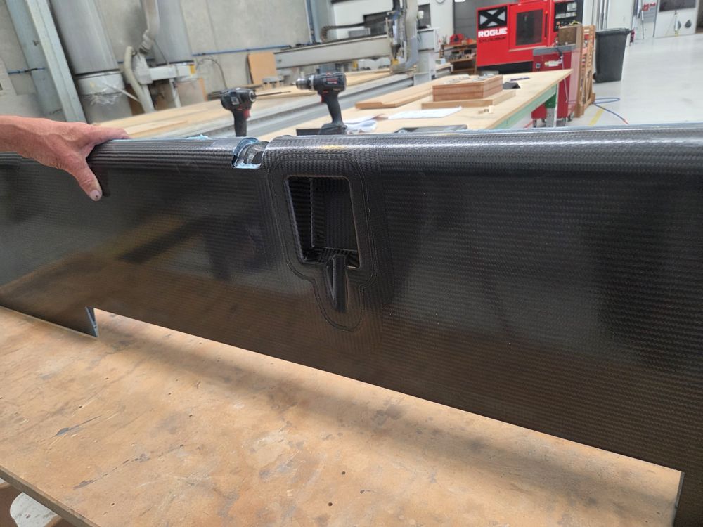
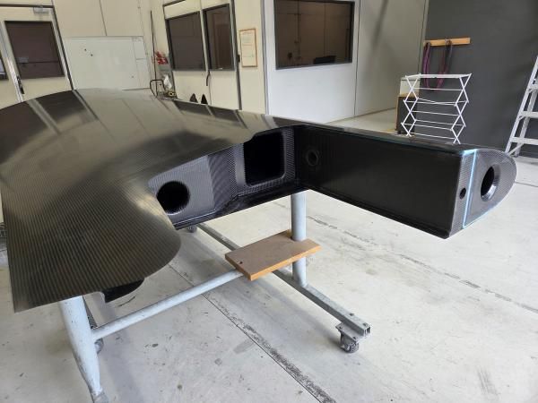
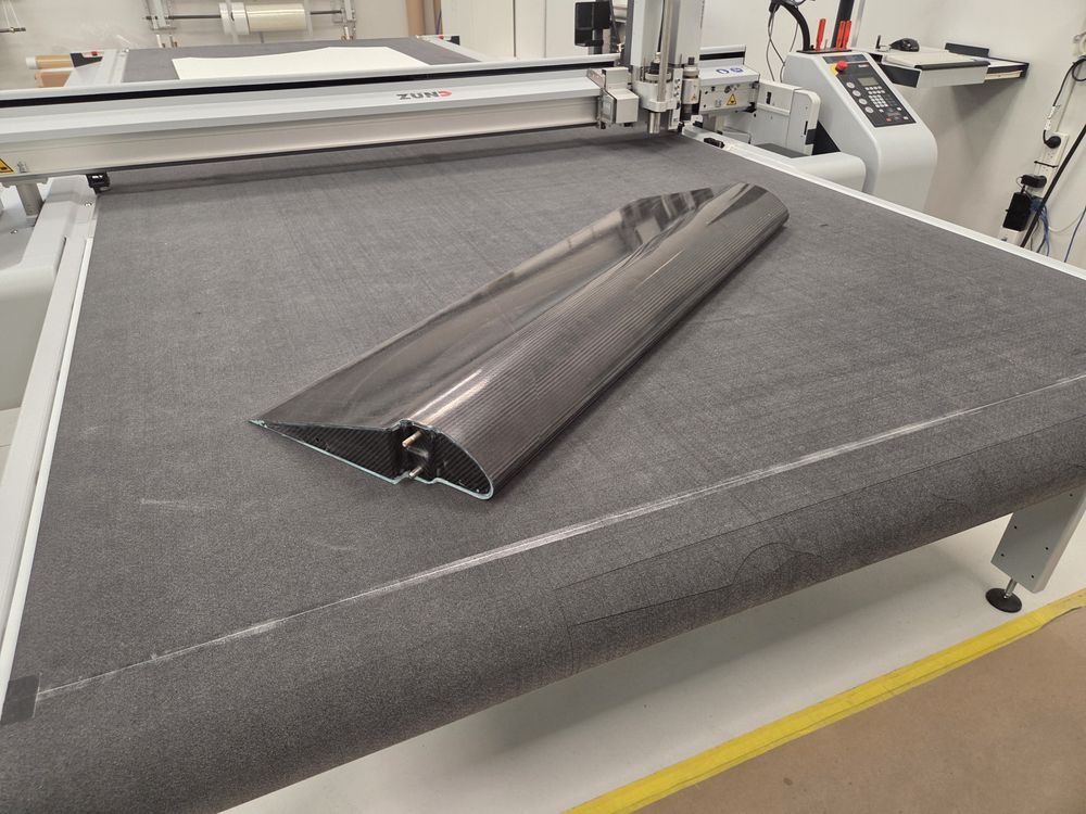
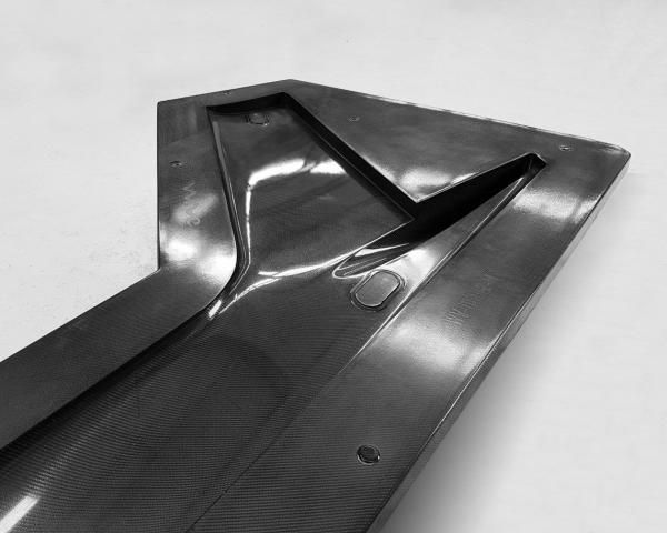
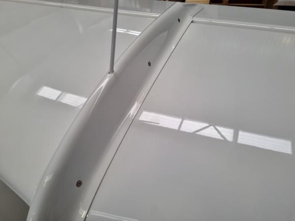
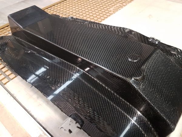
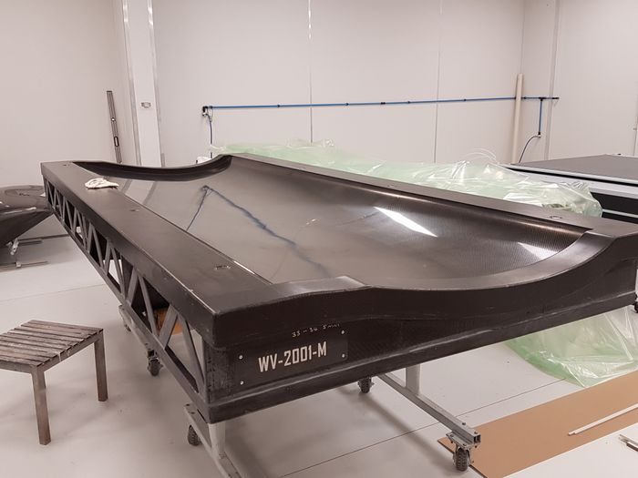
Above: Underside of Elevator showing Trim Motor cavity.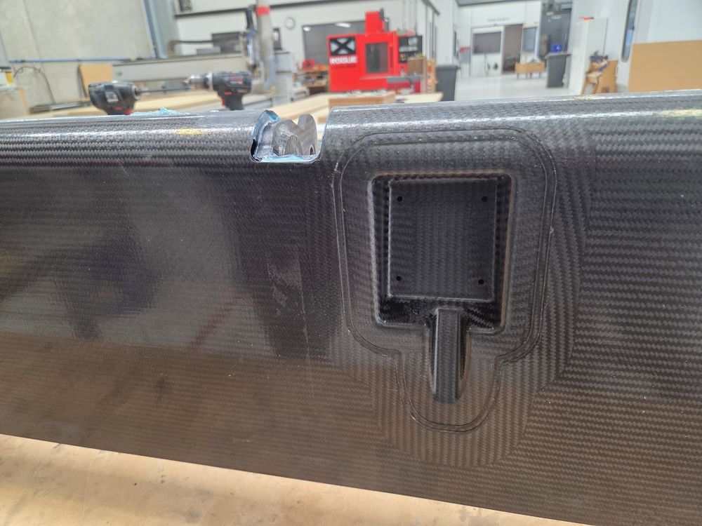
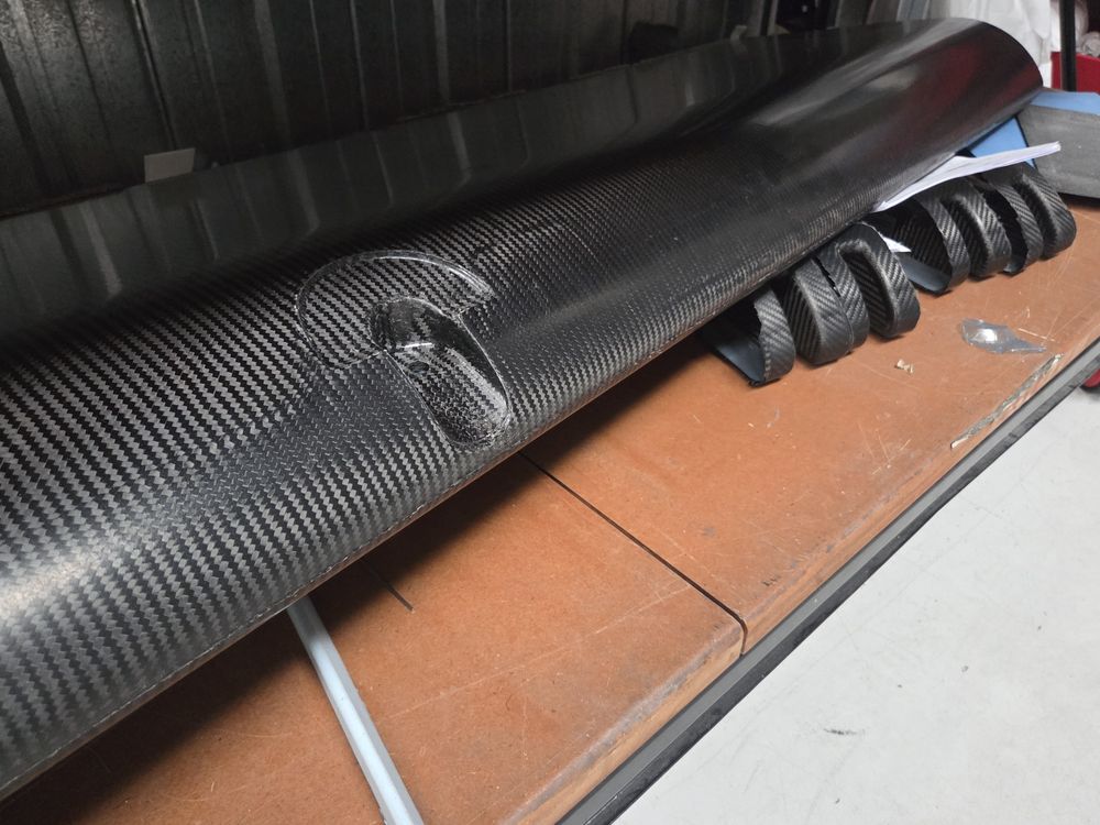
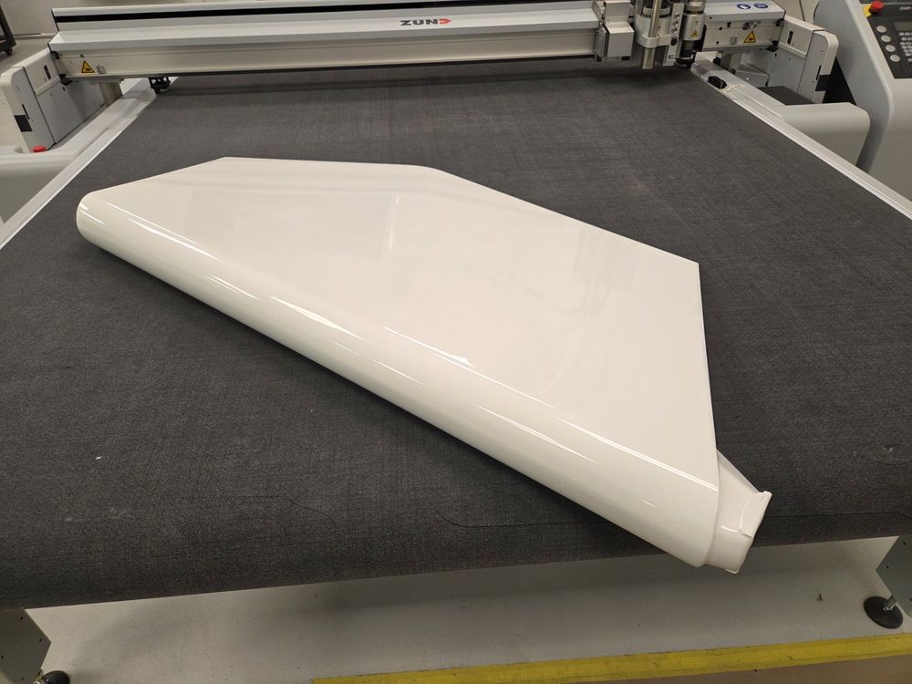
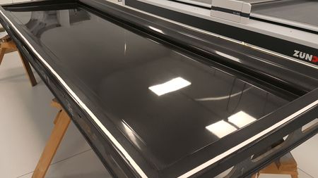
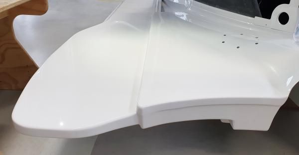
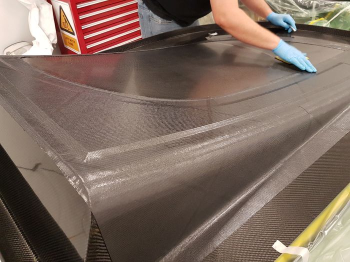
Above: Flap ready for bonding.
TESTING
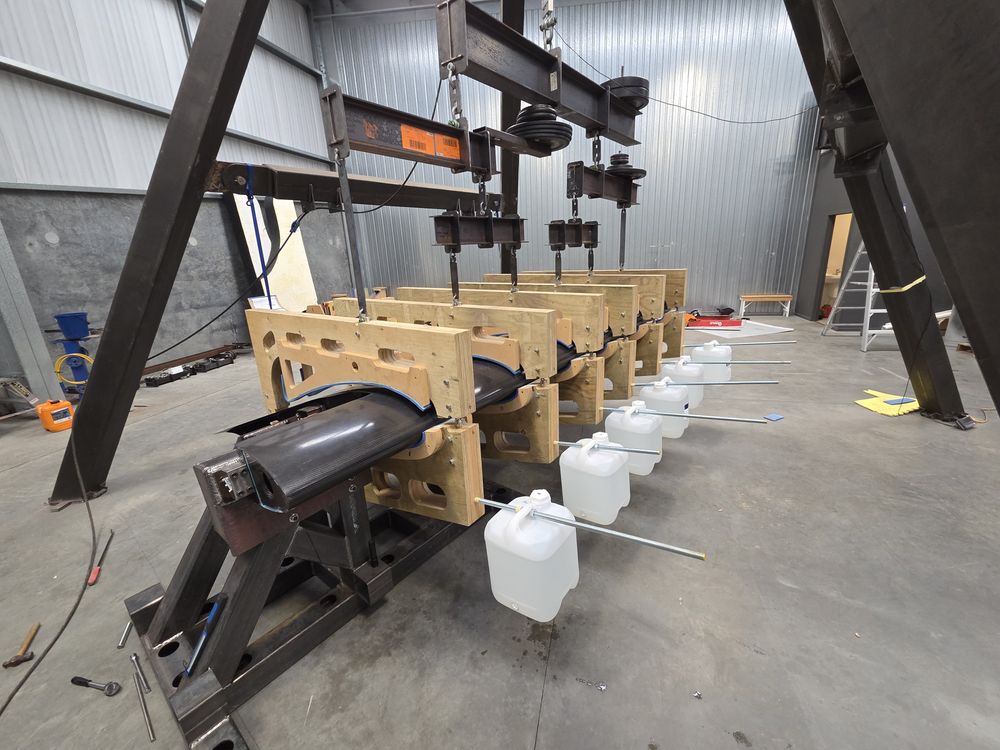
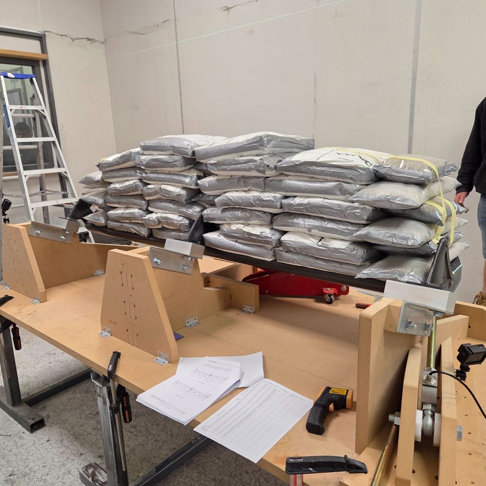
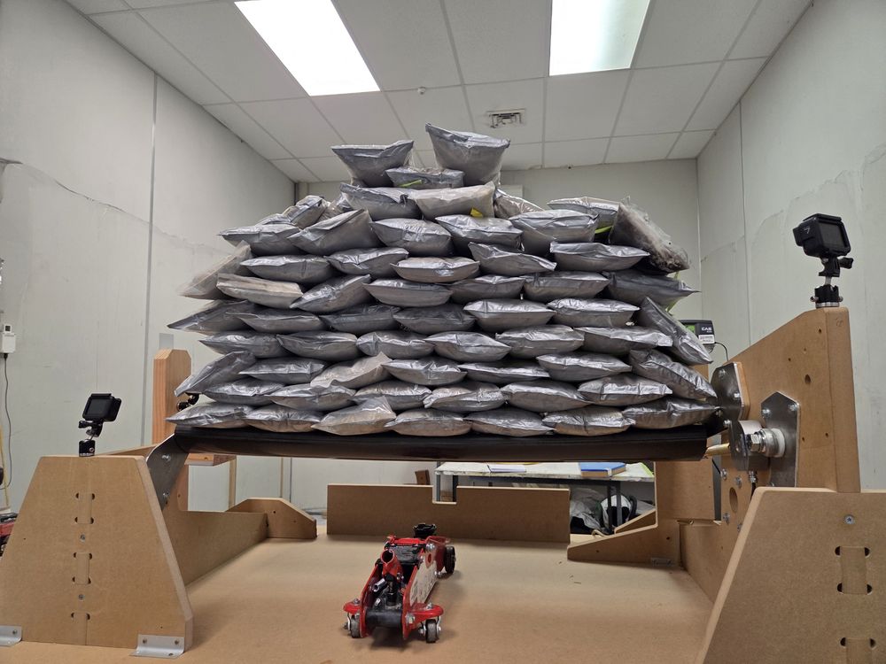
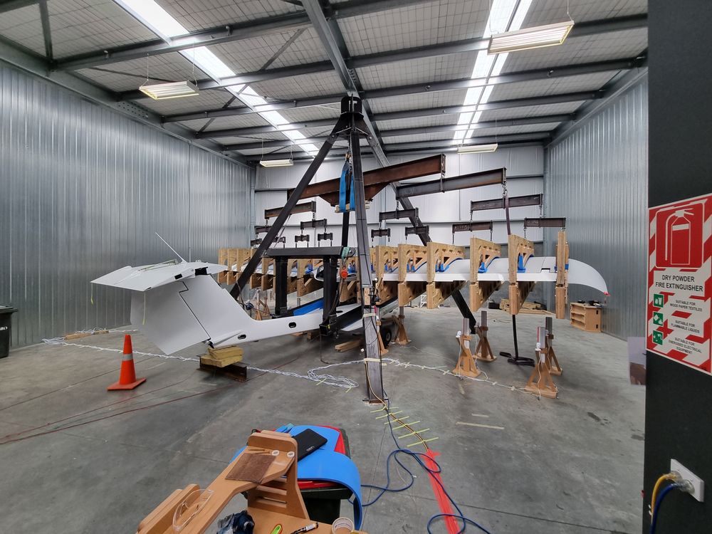
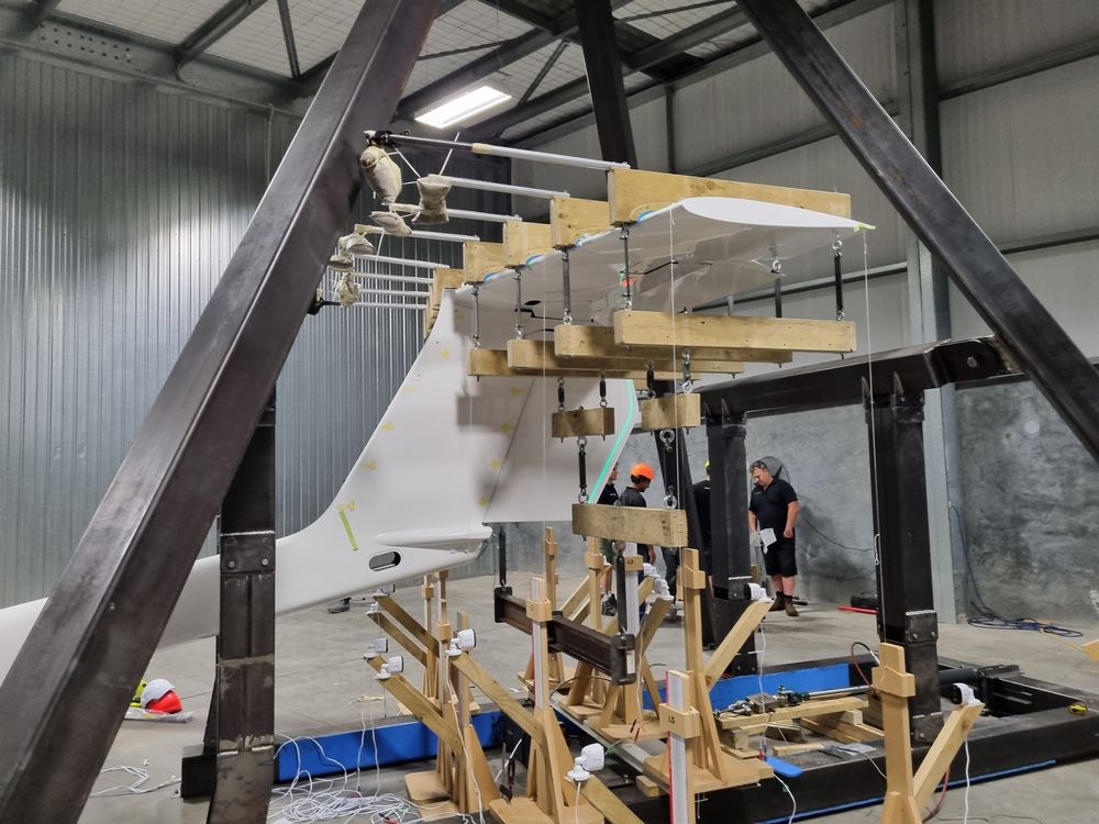
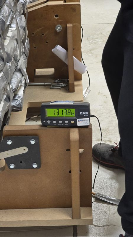
We test, test and test again. As an example, we conduct multiple wing structural tests; this is to ensure repeatability in both the manufacturing and testing processes. The next wing test performed will include the wing-side wing fold structure and the storage tube.
Production Engineering is in constant pursuit of weight saving, and we need to chase every ounce. The control surfaces have gone through this loop, and we then structurally test again to validate that the structural strength has been maintained.
We are working through complex fuel design issues, and currently having tests conducted in Canada. These tests include the fuel pump lifting requirements, both at room temperature, hot and cold, and at altitude as the fuel boils differently throughout these scenarios. This ensures that the fuel pumps can lift the required amount of fuel without vapor locking.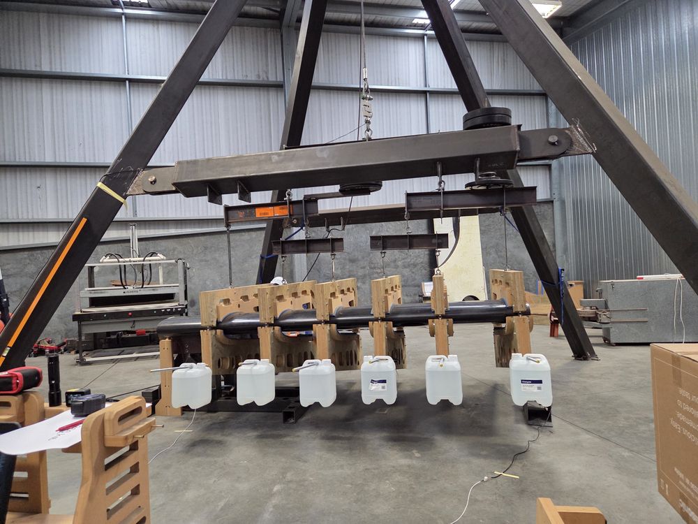
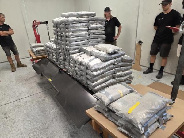
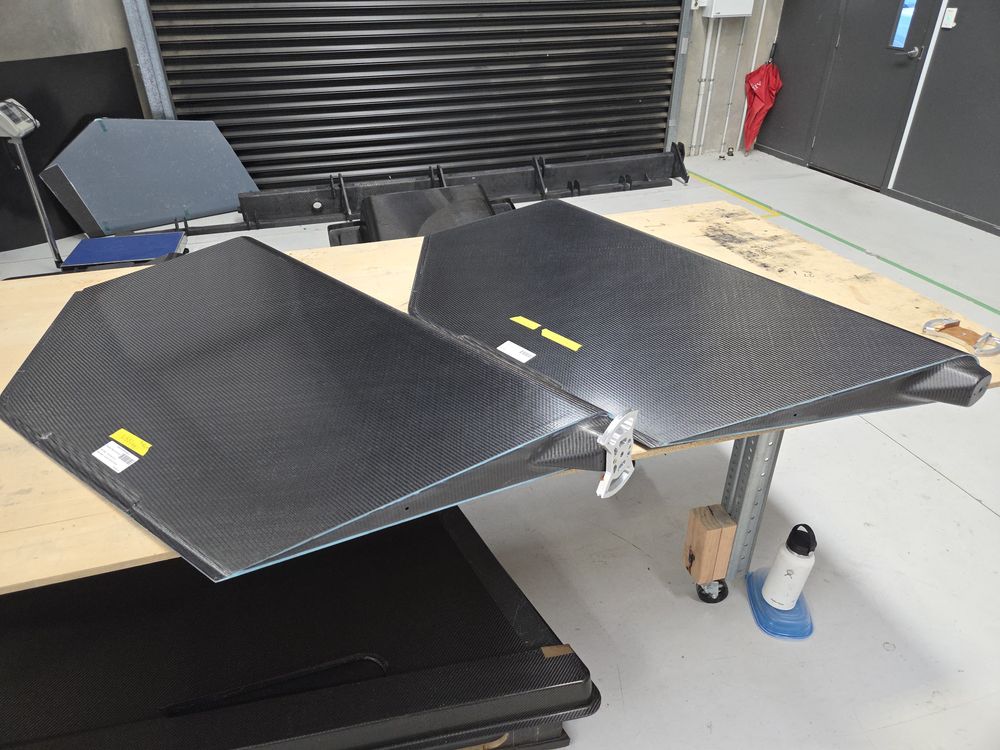
Above: Wing ready for structural testing. Previous testing resulted in wing being tested to 8.2Gs.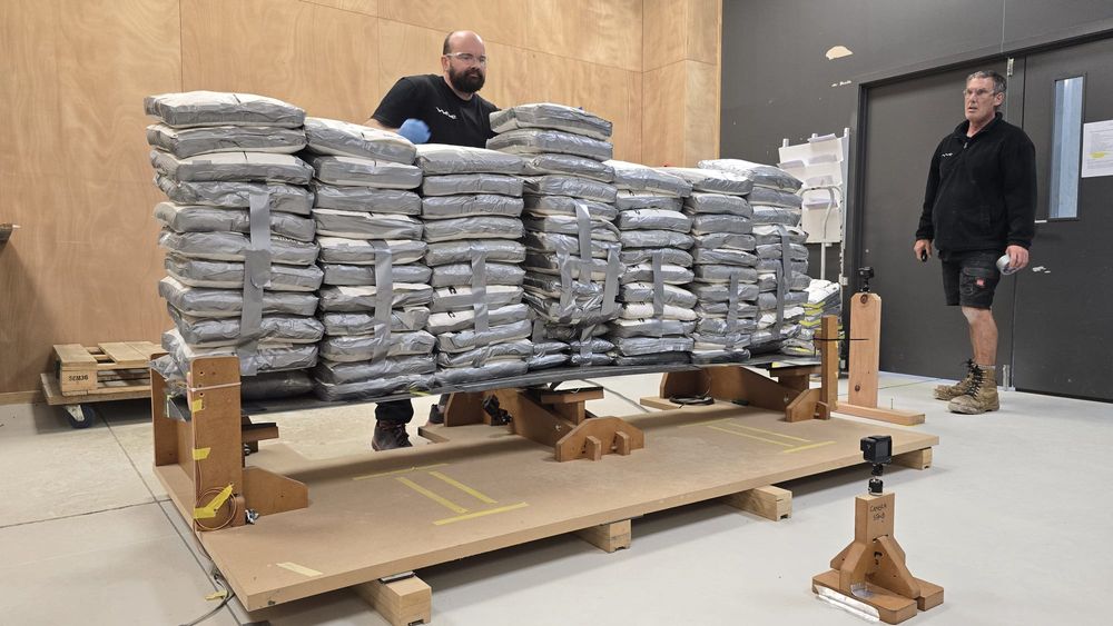
Above: Elevator structural testing after weight reduction.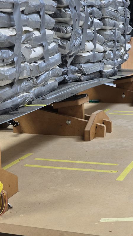
WING FOLD
The wing fold is in the final stages of design, with the wing side having been released for first article manufacture. First article manufacture is the first stage along the road to proving the part can be successfully made, is structurally sound and can be made repeatedly, within the allocated hours and to design specifications.
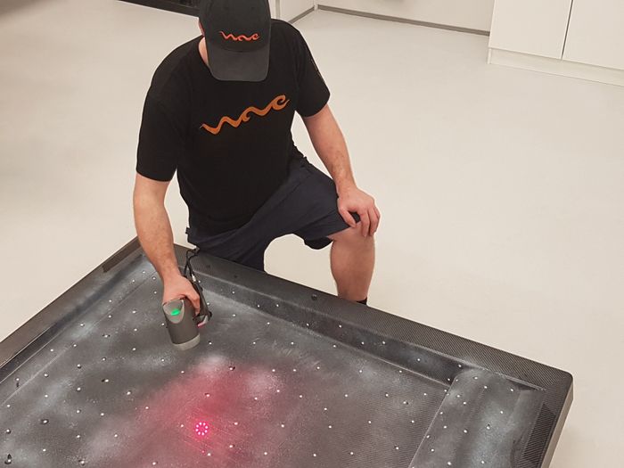
Once the first article has been made, 3D scanning is undertaken and a manufacturing review is conducted. If any changes are required it goes through the first article loop again, and again, if needed. Once the first article is accepted we then up issue the design to Revision 1.
At this stage it is approved for flight and can be batch manufactured. Each part and component are required to go through this process; this is an over simplified account but clearly explains what is required.
LANDING GEAR
Vickers are pleased to be manufacturing first articles for the nose landing gear. We are overcoming complex design issues with better ideas and revolutionary manufacturing processes that lead to the best amphibious gear design ever. We are satisfied with the results and are close to approval for Rev.1 manufacturing.
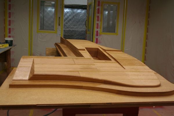
The main landing gear is in the early stages of plug manufacture; this is the first stage, to be shortly followed by the molds being made. The main gear is comprehensive in nature, as is the nose gear, but steady progress is being made.
Along with the structural components we are required to design and manufacture, there are multifaceted electrical and electronic aspects.
As with everything it must be custom designed, as the extension and retraction sequence is tailored to individual aircraft and is always aircraft specific. We must select and test actuators and design PCBs (Programable Circuit Boards) that perform our required tasks. Coupled with this hardware, custom firmware is required. Our in-house team are busy designing and manufacturing these elements for the landing gear, wing folding and water thrusters. Once initial design is complete testing with the landing gear will be done on our in-house designed and built testing rig. This rig will also be used to perform the structural drop testing in the coming months.
Once we release all this for manufacture, Rev.1, we will begin actuation reliability testing and cycle the gear many thousands of times to test for wear and breakage.
We recently took delivery of our Beringer wheels and brakes, factory modified for the WAVE to ensure maximum corrosion protection.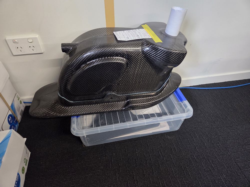
Above: Nose wheel housing assembly.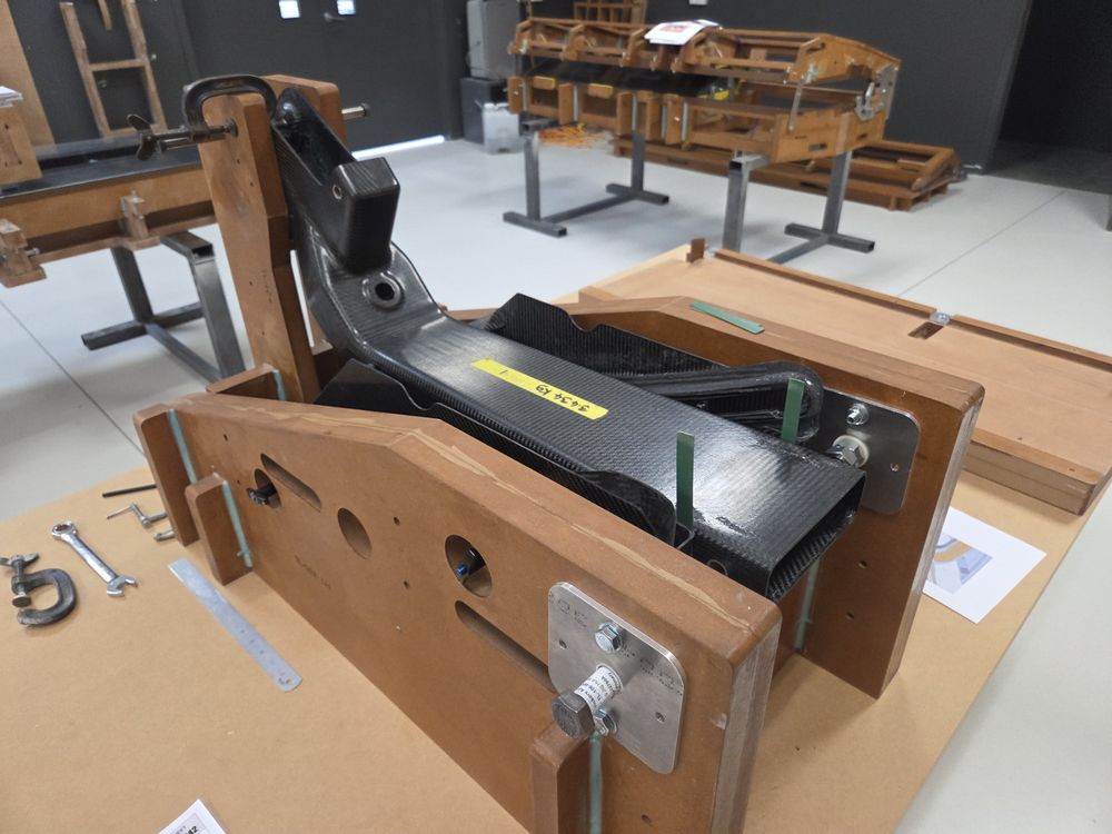
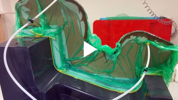
Above: Nose leg in bonding fixture. All bonding fixtures require in-house desgin and manufacture.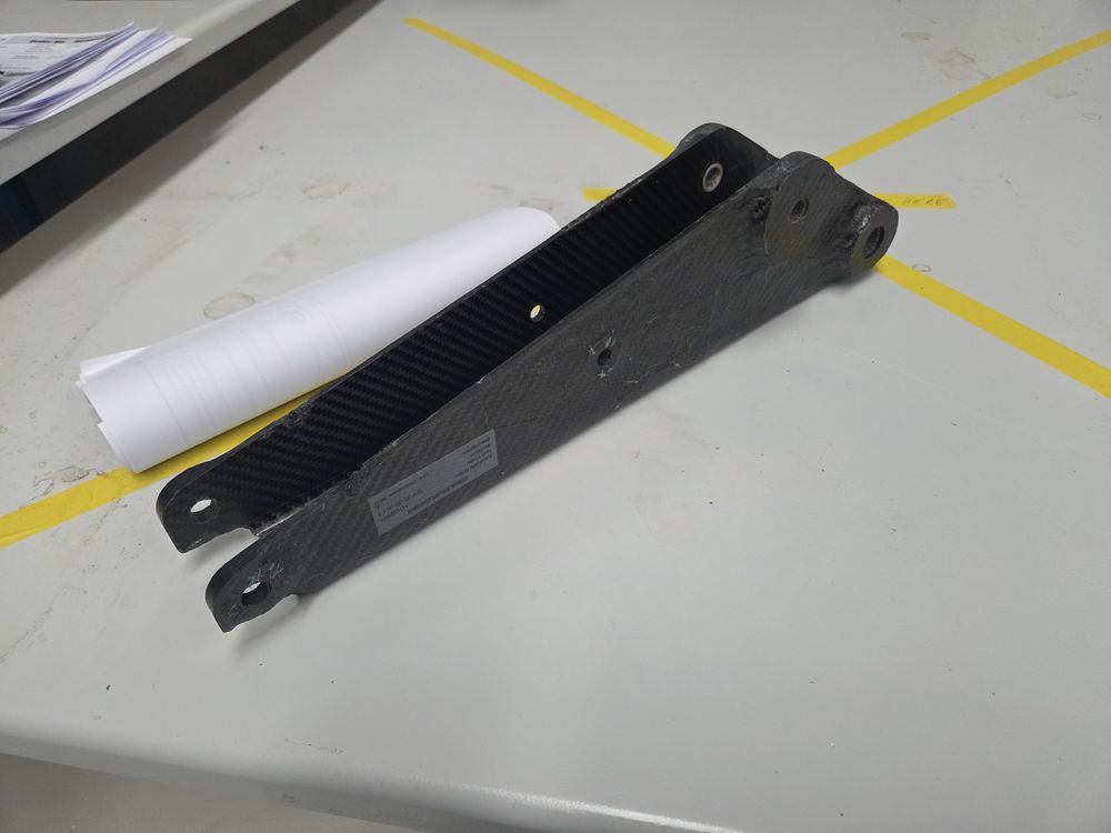
Above: Nose wheel assembly component.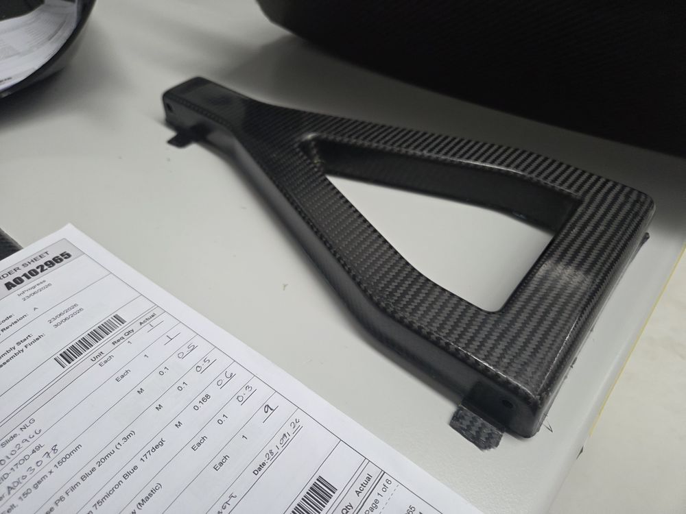
Above: Nose wheel assembly component, with accompanying documentation.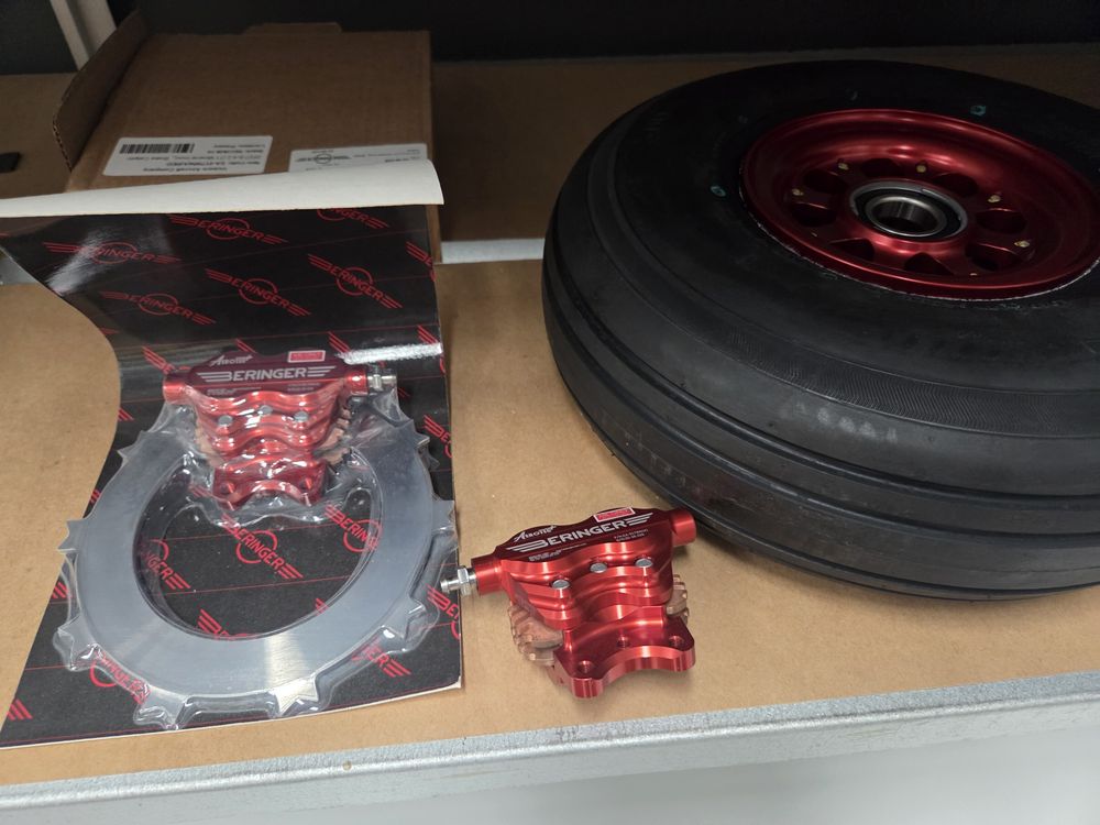
Above and below: Beringer wheel assembly components.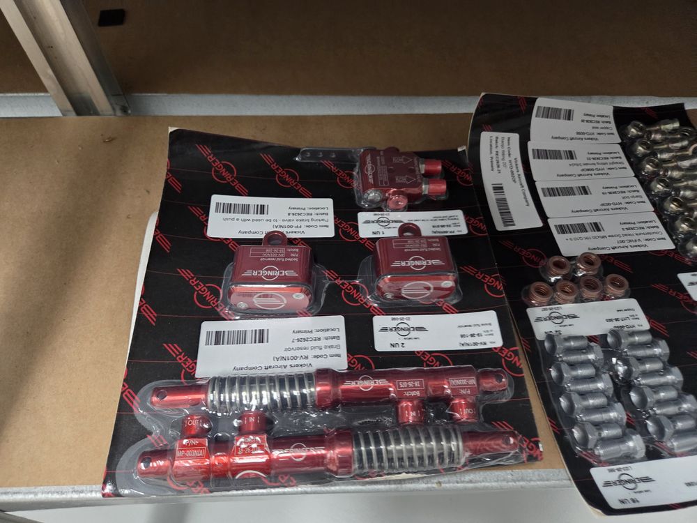
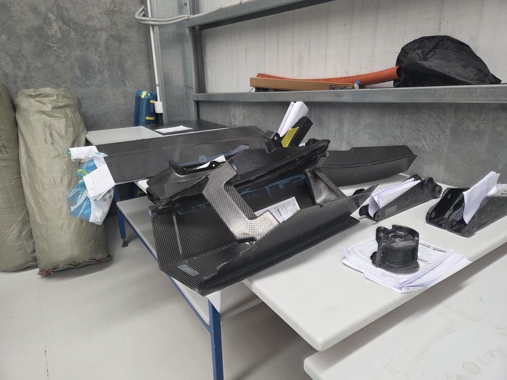
Above and below: Nose wheel components ready for bonding.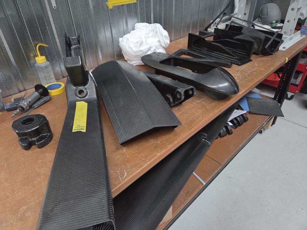
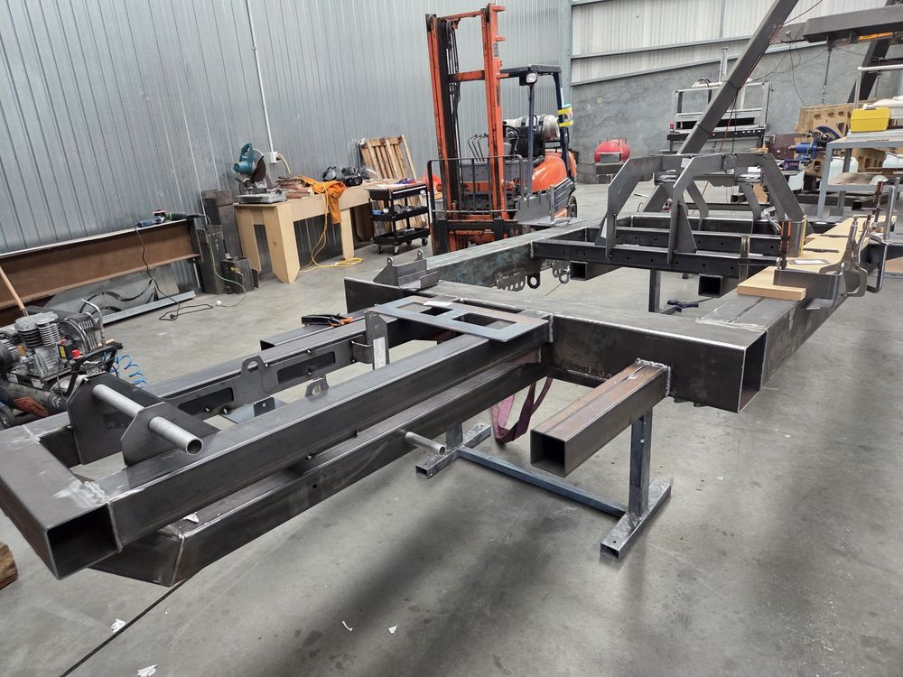
Above: Testing Rig for landing gear drop and functional testing. Designed and built in-house.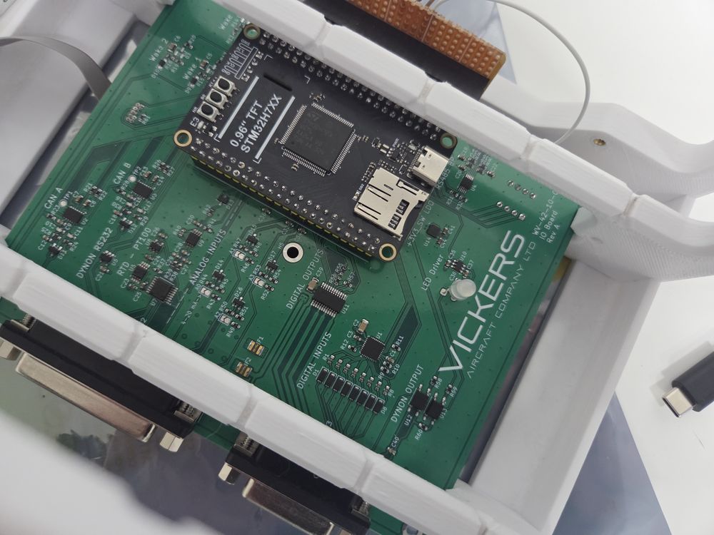
Above and below: Custom PCB boards for landing gear actuation.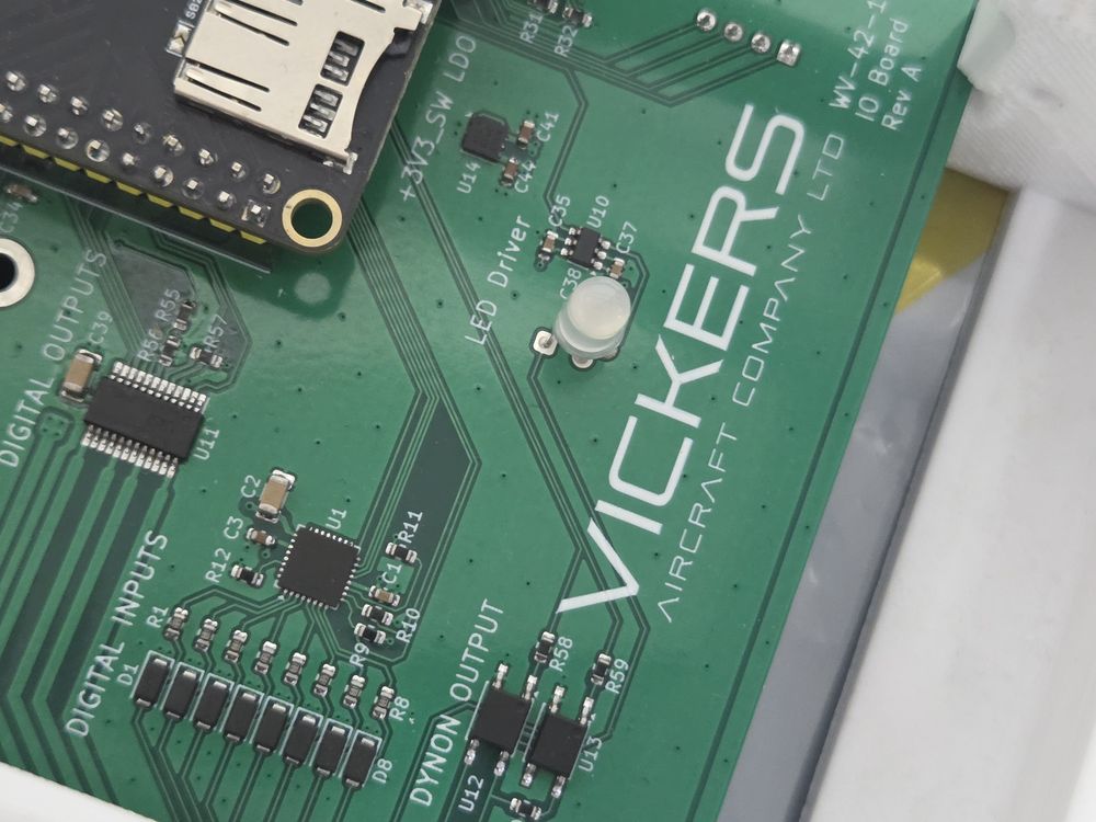
SCANNING
These folding H/Stab tip plugs are the next to go through mold build, part manufacture and then testing. They are scanned for fit against the original CAD model to ensure design tolerances are achieved. The below image shows the scan results, colored to show above and below tolerances.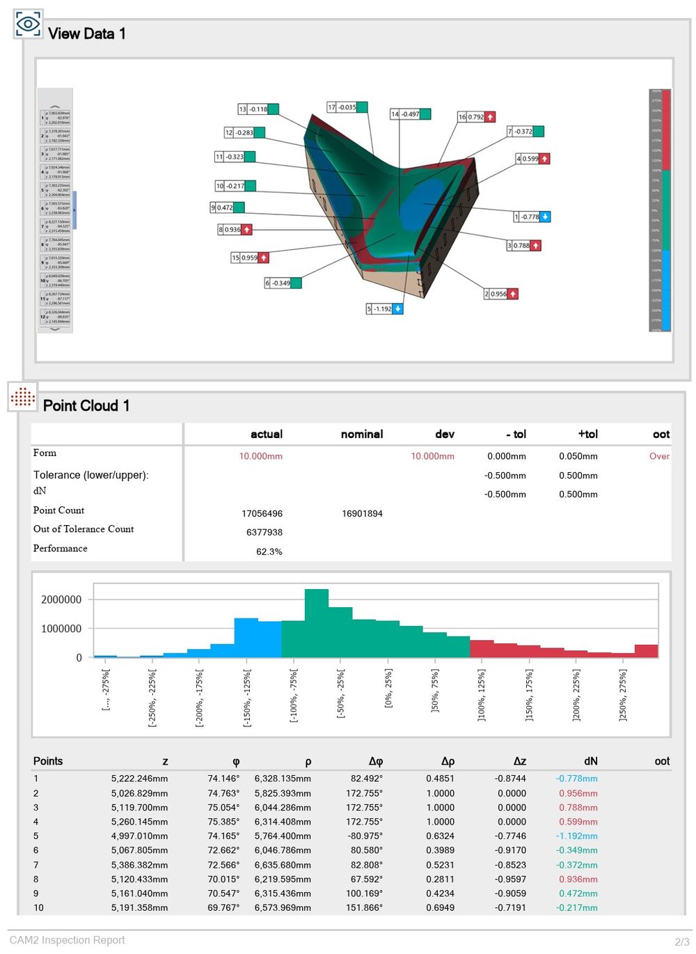
Above: 3D scanning report for HStab tip. Colors indicate upper and lower tolerances when compared to the CAD data.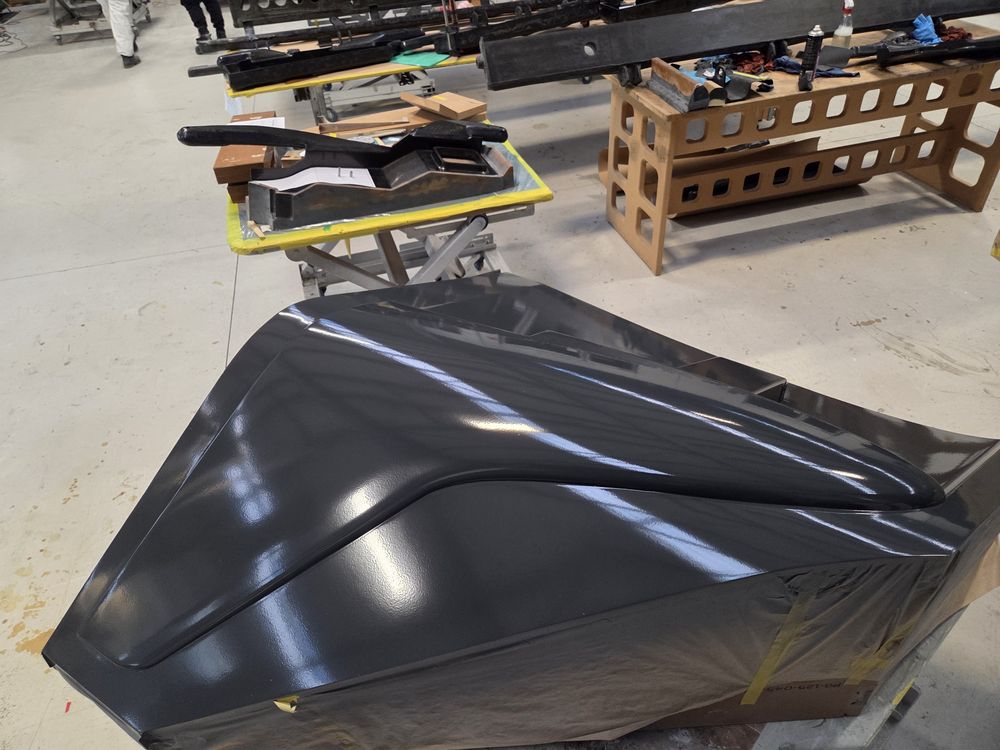
Above and below: Wingtip plugs ready to have molds taken from them.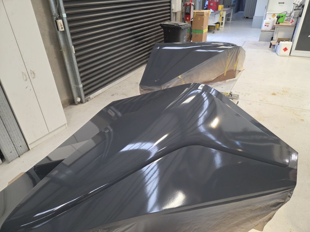
5-AXIS CNC
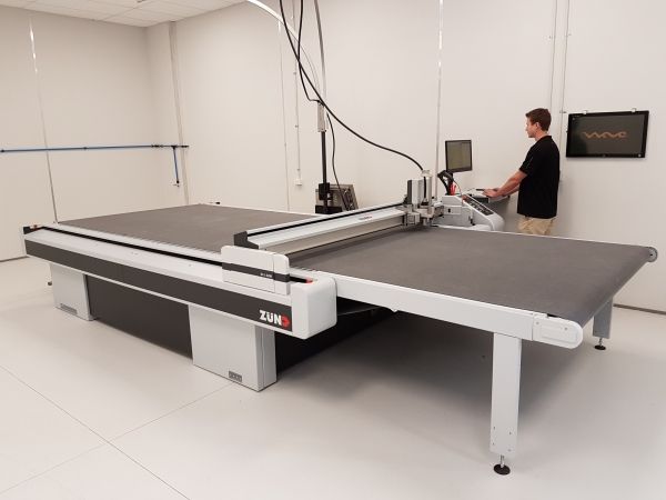
Our new and required 5-Axis CNC router will be operational in October, when we will put this on multi shift cutting cycles.
Below are CAD images of the new CNC, as you can see it is very large in size.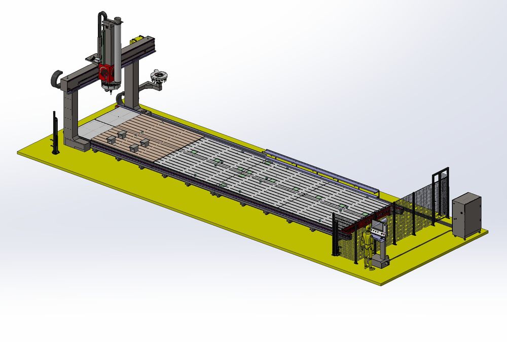
Above: The new 5-Axis CNC that will be operational in October.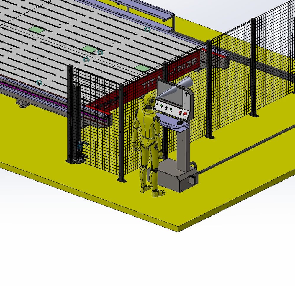
Above: A person standing at the control panel to show scale.
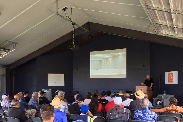
AIRVENTURE
INCREASED STAFF
As we push hard and ramp manufacturing, we have, and continue to, employ and train new staff. With this comes all the growing pains when you double and triple the staffing. What worked for 20 will not work for 50 or 60. New equipment is required alongside ramping staff.
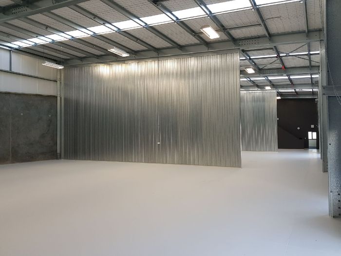
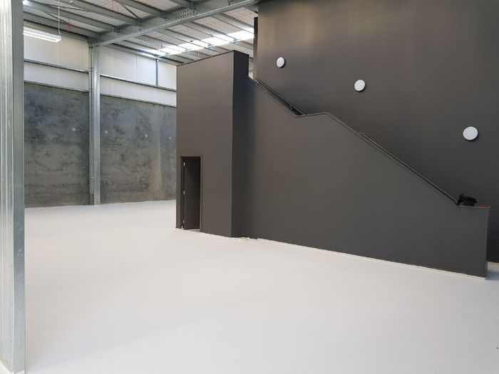
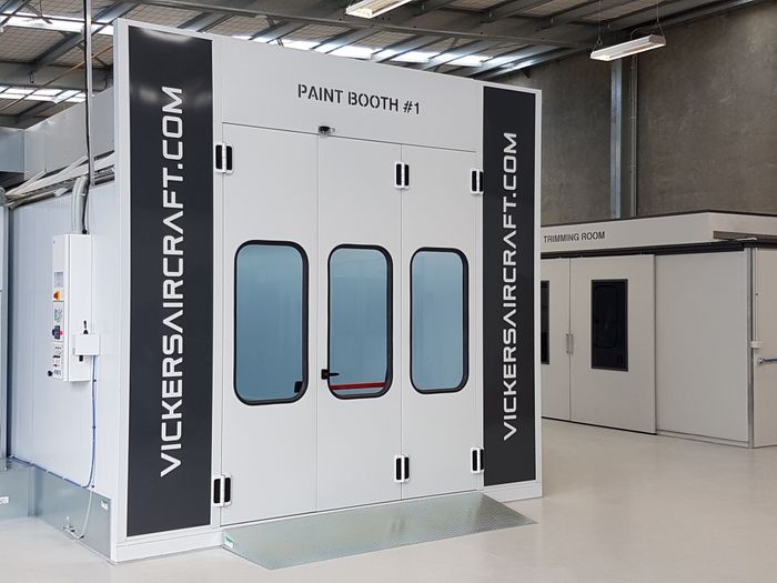
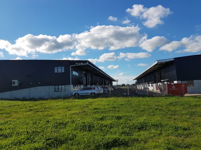
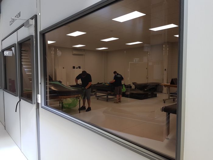
This includes the new CNC router, larger curing ovens and additional cleanrooms to ensure temperature control is achieved.
WATER LOADS
As best we can make out, the last time any real water loads were attempted was in the 40’s and 60’s with the old-style seaplanes of the day.
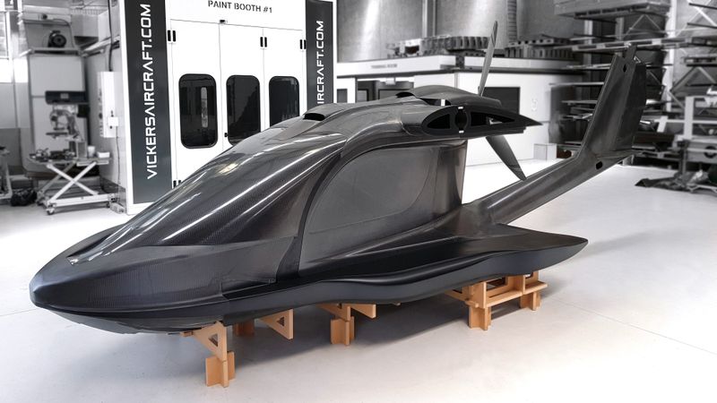
We have had to undertake the monstruous task of establishing the new standard. This entails thousands of potential load cases that the WAVE may experience, taking these and implementing a practicable and realistic set of real-world requirements that both structurally size the hull and fuselage, but also translate directly into the POH. These are also then used for structural G-load testing of the engine mount and tail plane.